Central supply systems for OP-lights according to VDE 0510 and VDE 0107 (OP- ZSV)
description
The battery, which works in standby parallel operation with the regulated rectifier, is charged up to a cell voltage of 2.275V (Pb-wf., min. 10 years according to DIN43539 part 4). In terms of power, the charging rectifier is designed to supply the connected operating lights under full load and to charge the discharged battery within 6 hours. At the moment of power failure the connected surgical lights are supplied from the battery for the prescribed autonomy time of at least one or three hours without interruption.
The battery intermediate circuit voltage of our systems is 36V. These 36V are reduced to the required lamp voltage of 24V by downward switching regulators. Each individual light branch receives its own, highly constantly regulated supply, which can be readjusted in the desired range. A monitoring unit is assigned to each light branch as well as a protective device which protects against too high operating voltages at the lamp.
Features, general
- I-V charging characteristic, according to DIN 41773
- mains isolating transformers according to VDE 0551
- complete protection of all relevant circles
- V/A-meter analog Kl. 1%; for charging voltage, rectifier/ consumer current
- Test device for “power failure”
- System functions indicated by LED on the outside of the housing and potential-free via terminal strip to the outside
- Collective disconnection device of the consumer circuits
- OP Lamp supply via compact, easily exchangeable switching regulator in 19″ rack, located in the housing door, convection-cooled version
display
Mains operation, battery operation, battery operation with mains available, battery circuit failure, DC overvoltage, DC undervoltage, battery deep discharge, OP circuit on, OP circuit failure (individual displays)
Message Outputs-General
All displays/fault messages are individually, potential-free connected to terminals, a collective fault message is also available as an option.
Message output control panels
For the connection of the external control panels in the operating room, the messages mains operation, battery operation, OP circuit on and OP circuit faulty are led out separately for each OP lamp with 36VDC potential. If necessary, these can also be designed for 24VDC or potential-free. The switch-on function is also available for each light circuit externally.
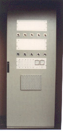
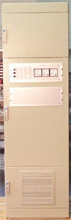
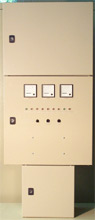
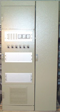
construction performances and dimensions
The systems we offer are manufactured to order. Construction work as well as dimensions depend on the requirements of the plant and would be communicated to you in the course of a written offer. Common to all systems is the spatial separation between connection/device/ and battery compartment.
Special designs
As special designs, systems with manual, unregulated bypass devices are available.
Other additional equipment will be offered to you on the basis of your inquiry.
Zentralversorgungsanlagen
Zentralversorgungsanlagen
Zentralversorgungsanlagen
Zentralversorgungsanlagen